
Wechat/Whatsapp: +86 135 6409 8916
Email: sales@oswellshunt.com
Wechat/Whatsapp: +86 135 6409 8916
Email: sales@oswellshunt.com
Packaging and Installation Tips for SMD Shunt: Introduction to Common Packaging Types and Installation Methods for SMD Shunt, such as SOT-23, SOT-223, SOIC, and Correct Soldering and Layout Techniques
Introduction:
SMD Shunt, or Surface Mount Device Shunt, is widely used in electronic circuits for current measurement and control. This article provides an overview of common packaging types for SMD Shunt, such as SOT-23, SOT-223, and SOIC, and offers tips for correct soldering and layout techniques to ensure proper installation.
Common Packaging Types:
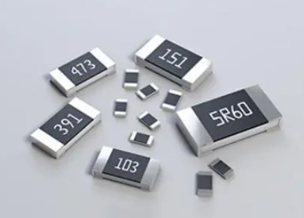
1. SOT-23: SOT-23 is a small outline transistor package with three or more pins. It is commonly used for low-power devices, including SMD Shunts. The pins are arranged in a triangular pattern, making it suitable for space-constrained applications.
2. SOT-223: SOT-223 is a surface mount package with four or five pins. It has a larger footprint compared to SOT-23 and is suitable for higher power applications. SOT-223 provides better heat dissipation capabilities due to its larger size.
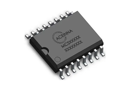
3. SOIC: SOIC, or Small Outline Integrated Circuit, is a surface mount package with a rectangular shape and gull-wing leads. It is commonly used for integrated circuits but can also be used for SMD Shunts. SOIC packages are available in different pin counts, ranging from 8 to 24.
Soldering Tips:
1. Soldering Temperature: Follow the manufacturer's recommendations for the soldering temperature and duration. Excessive heat can damage the SMD Shunt or surrounding components. Use a temperature-controlled soldering iron or reflow oven to maintain precise temperature control.
2. Soldering Method: There are two common soldering methods for SMD Shunts: reflow soldering and hand soldering. Reflow soldering is typically used for high-volume production and requires a reflow oven. Hand soldering involves using a soldering iron and solder wire. Ensure proper alignment and hold the SMD Shunt in place using tweezers or a vacuum pick-up tool.
3. Soldering Iron Tip: Use a fine-tipped soldering iron to ensure precise soldering. A smaller tip allows for better control and prevents excessive heat transfer to nearby components.
Layout Techniques:
1. Keep Traces Short: Minimize the length of traces connecting the SMD Shunt to other components. Shorter traces reduce the chances of signal degradation and improve measurement accuracy.
2. Separate High Current Traces: Keep high current traces separate from the SMD Shunt traces to avoid interference or voltage drops. This prevents inaccuracies in current measurements.
3. Thermal Management: Provide adequate thermal relief for SMD Shunts, especially in high-power applications. Ensure proper heat sinking and avoid placing heat-sensitive components near the SMD Shunt to prevent temperature rise and ensure stable operation.
4. Test Points: Consider adding test points near the SMD Shunt for easy access during testing or calibration. These test points enable convenient measurement of current without directly interfering with the SMD Shunt connection.
Conclusion:
Proper packaging and installation of SMD Shunt are crucial for reliable current measurement. Common packaging types like SOT-23, SOT-223, and SOIC offer different advantages based on power requirements and space constraints. Follow soldering tips such as maintaining proper temperature, using appropriate soldering methods, and employing a fine-tipped soldering iron. Additionally, consider layout techniques like keeping traces short, separating high current traces, implementing thermal management, and incorporating test points for easy access. By correctly packaging and installing SMD Shunt, designers can ensure accurate current measurement and improve the performance of their electronic circuits.
Next generation current sensor: for intelligent, high power systemNowadays, &quo...
2023-04-05 view+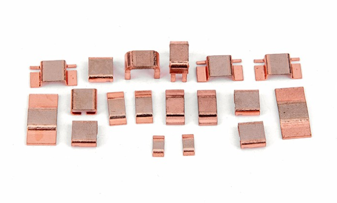
Patch resistance is mainly composed of four partsSubstrate:The substrate materia...
2023-03-18 view+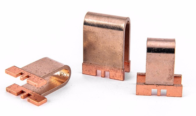
Selection of SMD resistance accuracy:The higher the precision of resistance, the...
2023-03-17 view+
Metal film resistors are widely used in electronic circuits for their precise an...
2023-09-29 view+

Tel:+86 21 68756810/90 Fax:+86-21-68671885-16
E-mail:sales@oswellshunt.com
Address: RM. 701-703,738 DONG FANG ROAD,SHANGHAI 200122,CHINA