
Wechat/Whatsapp: +86 135 6409 8916
Email: sales@oswellshunt.com
Wechat/Whatsapp: +86 135 6409 8916
Email: sales@oswellshunt.com
Next generation current sensor: for intelligent, high power system
Nowadays, "intelligent" products have become a hot topic in the development of electronic systems, especially for the performance and function of their related solutions. Under the double pressure of fierce competition and consumer expectations, products on the market must perform their functions as perfectly as possible through modern technology and techniques.
From new semiconductor materials to advanced solutions such as artificial intelligence, new technologies and approaches are creating new applications and reinventing existing ones. And all of this is driven by the evolution of digital technology in all aspects of electronic products.
")
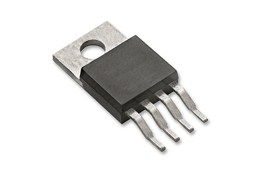
Figure 1: Current sensors used to regulate and manage power for a variety of applications
This development has led to a period of innovative growth, but it has also placed new pressures on system designers to choose the best system design options, especially those involved in monitoring circuit performance, to ensure that the products they develop are safe, efficient, reliable, and cost-effective. Advanced current sensing solutions can meet these needs.
For consumer and medical wearables, advanced personal electronics and the Internet of Things are, of course, smaller, more powerful and longer lasting. Likewise, industrial and automotive applications are pushing boundaries to achieve smaller, more efficient, and fewer thermal challenges. This can only be achieved by monitoring system performance in real time under any conditions.
Efficiency and performance
When it comes to electronic systems, it is important to balance efficiency and optimum performance. You can't just focus on efficiency and forget about the timeliness of the system. It can also fail to respond to applications on demand in a timely manner during difficult operations, thus losing value for money. Only by monitoring power usage in real time can both be taken into account during operation.
If your product is not accurate enough, the feedback is not good and the product will not be competitive. Current sensing can be embedded into intelligent systems contactless, providing critical performance information needed for self-management, so it does not have to be a major infrastructure element in the design.
The evolution from traditional passive systems to intelligent solutions (intelligent feedback and control) has brought significant improvements to system operation. Overall, power efficiency and motor drive open-loop current sensing accuracy are very beneficial for improved operation in the full temperature range. With the continuous development of industry 4.0 and process requirements, the new goal now is to improve performance at temperatures up to 85°C or 105°C.
In the field of advanced solar inverters, the system achieves a higher level of accuracy in the ultra-high temperature range. Similarly, applications that require high accuracy and an extremely wide dynamic range will require higher temperature accuracy and can implement a single closed-loop current sensing system rather than two open-loop current sensors to track low and high currents.
Thermal management problem
One of the basic principles of electronics is that power management is thermal management. Power efficiency and thermal performance go hand in hand because the energy wasted from the system is always in the form of heat. That is, if you can improve efficiency, you can lower the temperature, and your electronics can function better and more reliably.
On the other hand, if your electronics don't work well, you generate more waste heat, which leads to more heat management, reliability and safety issues. Therefore, optimizing power efficiency and thermal management will significantly improve productivity, cost-effectiveness, safety and reliability.
We are familiar with inverters, motor drives, power supplies, UPS and external charging stations. They must be able to withstand the temperature test, operating in the temperature range of -40°C to 85°C, and even ambient temperatures often as high as 105°C.
Even if the power system in inverter applications has a relatively low internal maximum temperature, it is usually required to operate at 85°C, at least to ensure proper operating space without derating. Ambient operating temperatures can be as high as 125°C for an on-board charger and 105°C to 150°C for a motor driver, depending on its location.
Although many systems use fans and other temperature regulating mechanisms to manage system thermal performance, this can be difficult for systems with fast temperature changes and high dynamic performance. In addition, external cooling devices take up space that could be used for other designs, consume additional energy and interfere with their own efficient operation.
For systems with rapid temperature changes, measuring system current is an efficient way to predict and manage system thermal performance. Monitoring the effective flow of electricity to the management controller can determine if current strength is rapidly increasing and predict potentially catastrophic failures to protect systems and critical components.
System performance, system reliability, or basic safety fault identification, all of which need to be addressed urgently. Current sensing is one such way to detect potential problems, minimize system downtime, and prevent catastrophic failures.
Timing and performance
Since the power factor correction (PFC) stage is also a time oriented system, synchronization and regulation are important factors to be considered in advanced power systems. The output ripple of the circuit must be filtered to avoid current distortion, and the loop frequency is related to the system bandwidth.
Think of the PFC stage as a system that delivers power and is managed by a control signal that measures the current during each power switch cycle to obtain the current for each cycle, even if the system control loop bandwidth is low. Under ideal conditions, the gain response is flat only when the multiples of switching frequency are high, and the phase margin at switching frequency is low. Low frequencies work, but there is some effect on gain and phase delay at switching frequencies.
Although the total control loop bandwidth may be much lower than the switching frequency, current measurements should be made at the switching frequency for cycle by cycle control. Most totem pole PFCS switch between ~65 kHz and 150 kHz, ideally requiring a bandwidth of 650 kHz (at least >300 kHz) to 1.5 MHz. In some cases, this switching frequency is pushed up to 300 KHZ in the pre-design, requiring about 3 MHz bandwidth (at least 1.5 MHz bandwidth).
Power conversion with high current up to 1000A, usually using IGBTs and silicon MosFeTs at levels below 1khz to 20khz. Other circuits can be switched to about 40-50 kHz using broadband silicon carbide (SiC)/ gallium nitride (GaN) power switches, and further developments in the SiC/GaN power level may eventually move this high-current switch to 100 kHz, requiring bandwidth from 500 kHz to 1 MHz.
With a high current power conversion of up to 1000A, it switches at levels below 1kHz to 20kHz using IGBTs and silicon MosFETs. Other circuits can be switched to approximately 40-50 KHZ using a wideband Silicon Carbide (SiC)/gallium nitride (GaN) power switch. And with further development of SiC/GaN power levels, it is possible to eventually move this high-current switching to 100kHz, which requires a bandwidth of 500 kHz to 1 MHz.
Lack of precision, the feedback is not good
To achieve these levels of performance, accurate measurements must be made using high-precision current monitoring, and the latest current sensing systems, such as AmR-based isolated current sensors, offer significant performance advantages over traditional solutions. It can provide high-precision, high-bandwidth sensing in a single chip with best-in-class performance in bandwidth, output step response, and accuracy.

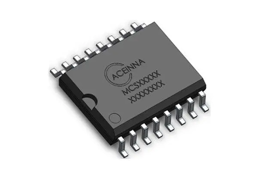
Figure 2: AmR-based isolated current sensors provide high precision, high bandwidth sensing
The new nano current sensor is a highly integrated, isolated bidirectional current sensor based on AMR technology. The MCx1101 series includes ±5A, ±20A, and ±50A products in an SOIC-16 package with A low impedance (±50A at 0.9mΩ) current path and is UL/IEC/EN certified for isolation applications. It provides higher DC accuracy and dynamic range than conventional and existing solutions. For example, a ±20A product with a typical accuracy of ±0.6% will achieve a ±2.0% (maximum) accuracy at 85°C.
The Shiner current sensor guarantees a ±0.3% temperature offset of ±60 mA or FSR (maximum), thus achieving high accuracy in the current range of approximately 10:1, a significant improvement over the dynamic range of Hall sensor-based devices. Its features include 1.5MHz signal bandwidth, low phase delay, fast output step response of 300 ns, and 4.8kV isolation, making it ideal for current sensing in fast current control loops and protection for high-performance power supply, inverter, and motor control applications.
conclusion
The research and development of automation solutions for optimal power and motion control is a difficult task, which will lead to sub-optimal performance unless the system is well designed. Choosing the right components, equipment, and methods to address power, performance, and thermal management issues will greatly ensure that your final power solution delivers the desired performance in the best way, improving efficiency and cost effectiveness.
I am very honored to introduce Vishay resistors to everyone as a professor at Pe...
2023-06-23 view+
Selection of SMD resistance accuracy:The higher the precision of resistance, the...
2023-03-17 view+
Shunt resistors play a crucial role in current sensing and measurement applicati...
2023-10-31 view+
The 2726 Low Resistance Power Resistors offer a maximum power rating of 5W, a re...
2023-05-07 view+

Tel:+86 21 68756810/90 Fax:+86-21-68671885-16
E-mail:sales@oswellshunt.com
Address: RM. 701-703,738 DONG FANG ROAD,SHANGHAI 200122,CHINA